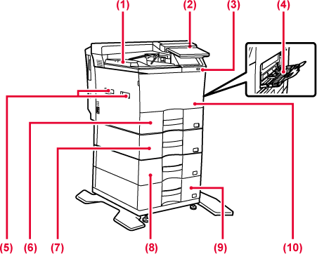
Printed papers are delivered to this tray.
This panel hosts the [Power] button, Information indicator and touch panel.
Use the touch panel to operate each of these functions.
An NFC touch point area mark also appears.
This is used to connect a USB device such as a USB memory device to the machine.
Supports USB 2.0 (Hi-Speed).
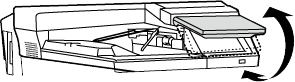
Use this tray to feed paper manually. When loading paper, also open the extension
tray.
Grasp it when moving the machine.
Store paper in this tray.
Store paper in this tray.
Store paper in this tray.
Store paper in this tray.
Open this cover to replace a toner cartridge.
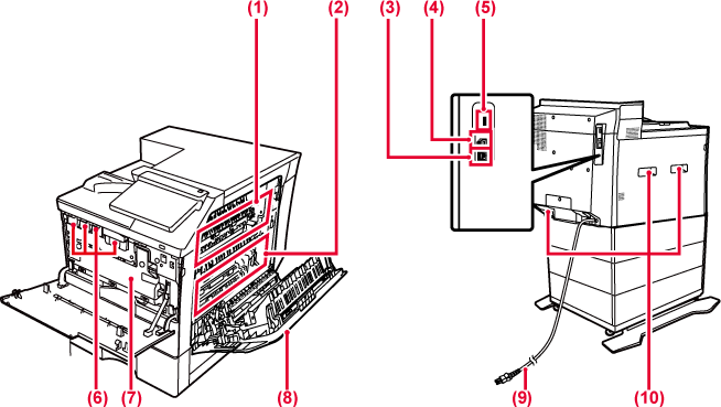
Heat is applied here to fuse the transferred image onto the paper.
Warning
The fusing unit is hot. Take care not to burn yourself when removing a misfeed.During full color printing, the toner images of the four colors on the photoconductive
drums are combined together on the transfer belt.
During black and white printing, only the black toner image is transferred onto the
transfer belt.
Caution
Do not touch or damage the transfer belt.Connect the LAN cable to this connector when the machine is used on a network.
Use a shielded LAN cable.
The machine does not use this connector.
This is used to connect a USB device such as a USB memory device to the machine.Supports
USB 2.0 (Hi-Speed) and USB3.0 (SuperSpeed).
This cartridge contains toner.
When the toner in a cartridge runs out, replace with new one.
This container collects excess toner that remains after printing.
REPLACING THE TONER COLLECTION CONTAINER
Open this cover to remove a paper misfeed.
And open when user changing the setting to print envelope.
Grasp it when moving the machine.
This section describes the names and functions of the respective parts of the operation
panel.
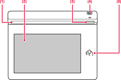
This indicator illuminates when the power to the machine is turned on, and when a
user logs in to the machine.
Messages and keys appear on the touch panel display.
Operate the machine by directly tapping the displayed keys.
This indicator lights up when the machine's power switch is on the position. Blinks
blue during the time that the [Power] button does not operate immediately after the
power plug is inserted into the power outlet.
Use this button to turn the machine on and off and to enter the power saving mode.
NFC can be used when connecting to Synappx Go. For more information, see the Synappx
Go manual.
Caution
When turning the machine power ON/OFF; at user authentication when the user has logged
in using IC card or NFC; when connecting USB memory to the machine; when starting
a job on the machine control panel; or during image adjustment or when adding toner;
an error has occurred in the machine, the LED lights blue and orange in response to
the request/operation from the user to communicate to the user the machine status.
Lighting patterns differ depending on status.
| Lighting color | Lighting patterns | Status |
|---|---|---|
|
Blue |
Pattern 1 |
Job in progress, such as paper feeding or output. |
|
Pattern 2 |
Ready state or other state where jobs can be accepted. |
|
|
Orange |
Lights* |
Errors that do not stop machine operation, such as almost out of toner. |
|
Blinks* |
Errors that stop machine operation, such as misfeeds and out of toner. |
* If the lighting state and the blinking state overlap, the blinking state takes priority.
Version 02a / bpc545pw_usr_02a_us
